In our previous post, we explained how power factor can manipulate your energy consumption. Now that you are aware of the problem, it’s time for you to understand the solution. Caution: We expect you to have a bit of a technical background and some basic knowledge of currents and voltages before you proceed.
Power factor is nothing but a representation of reactive power required by the load (froth on the beer). The need for utility to supply reactive power can be eliminated if it is made available at site. Correction capacitors are installed to meet this requirement.

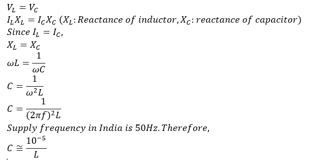
On the left, you can see a very basic circuit diagram showing power supply from the grid, active and reactive loads (R and L, respectively) and a capacitor bank, C. When currents flowing through capacitor bank (IC) and reactive load (IL) match, grid is only supposed to feed the active load (IR). Power factor in such a case would be equal to 1.

Thus, for matching impedances, you require a capacitor of above mentioned capacitance.
What becomes challenging though is that the reactive load on demand side (L) is not fixed. It keeps on varying with the load. Therefore, consumers require multiple capacitors of relevant sizes. APFC (Automatic Power Factor Correction) is thus installed to provide flexibility of switching between different capacitors based on the running load.
For instance, consider a capacitor bank with 3 capacitors of 5kVAr, 10kVAr and 15kVAr. Assume there is a running reactive load of 8kVAr. In this case, capacitor of 5kVAr will be kicked in to meet the requirement, thereby reducing the net reactive load to 3kVAr. Now consider the scenario in which capacitor bank consisted only 1 capacitor of 30kVAr. Since the running reactive load is only 8kVAr, capacitor bank won’t get kicked in as otherwise net reactive load would become 22kVAr (|30kVAr–8kVAr|). Therefore, it is necessary to have multiple capacitors so as to make it possible to cater to small reactive loads as well.
